
TIM3 has 4 PWM channels available, however I only have 2 oscilloscope probes so I will set up 2 channels only.
PWM frequency: 10kHz
Duty cycle: Channel 1 - 50%, Channel 2 - 25%
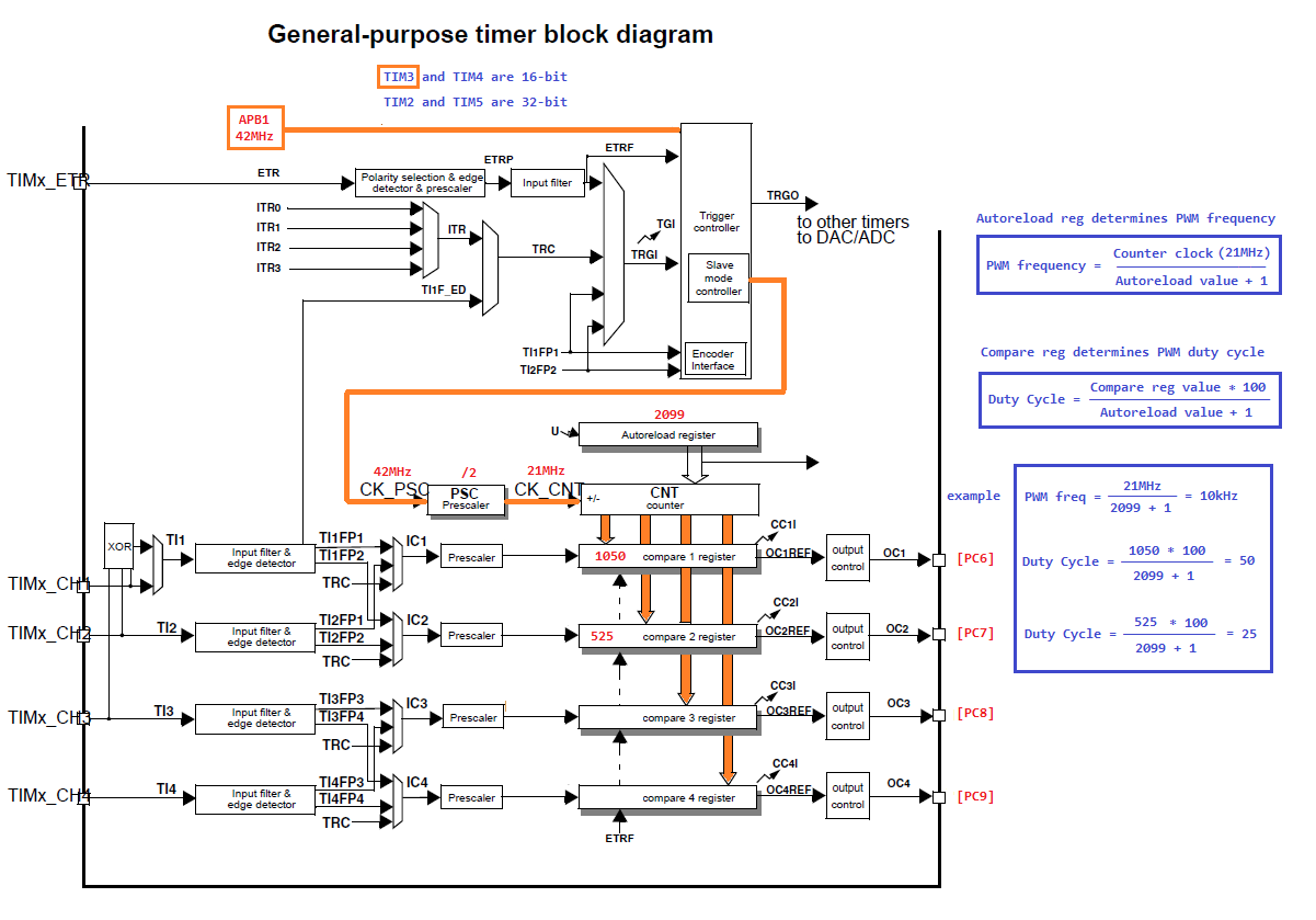
@output [Channel 1 - PC6], [Channel 2 - PC7]
#include <stm32f4xx.h>
#include "other_stuff.h"

#define   APB1_FREQ       42000000                            // Clock driving TIM3
#define   CNT_FREQ        21000000                            // TIM3 counter clock (prescaled APB1)
#define   PWM_FREQ        10000                               // PWM frequency in (320Hz~21MHz) range
#define   PWM_DC_CH1      50                                  // Channel 1 duty cycle
#define   PWM_DC_CH2      25                                  // Channel 2 duty cycle

#define   TIM_PULSE_CH1    (((PWM_DC_CH1) * (APB1_FREQ)) \
                          / ((PWM_FREQ) * (200)))             // Output Compare 1 reg value
#define   TIM_PULSE_CH2    (((PWM_DC_CH2) * (APB1_FREQ)) \
                          / ((PWM_FREQ) * (200)))             // Output Compare 2 reg value
#define   TIM_PERIOD       (((CNT_FREQ) / (PWM_FREQ))-1)      // Autoreload reg value
#define   TIM_PRESCALER    (((APB1_FREQ) / (CNT_FREQ))-1)     // APB1 prescaler


int main()
{

  GPIO_InitTypeDef        gpio_C;                             // GPIOC structure
  TIM_TimeBaseInitTypeDef TIM3_TimeBase;                      // Time Base structure
  TIM_OCInitTypeDef       TIM3_OC;                            // Output Compare structure

  RCC_AHB1PeriphClockCmd(RCC_AHB1Periph_GPIOC, ENABLE);       // Clocking GPIOC (AHB1 = 84MHz)
  RCC_APB1PeriphClockCmd(RCC_APB1Periph_TIM3, ENABLE);        // Clocking TIM3  (APB1 = 42MHz)

  gpio_C.GPIO_Pin   = GPIO_Pin_6 | GPIO_Pin_7;                // Ch.1 (PC6), Ch.2 (PC7)
  gpio_C.GPIO_Mode  = GPIO_Mode_AF;                           // PWM is an alternative function
  gpio_C.GPIO_Speed = GPIO_Fast_Speed;                        // 50MHz
  gpio_C.GPIO_OType = GPIO_OType_PP;                          // Push-pull
  gpio_C.GPIO_PuPd  = GPIO_PuPd_UP;                           // Pulling-up
  GPIO_Init(GPIOC, &gpio_C);                                  // Initializing GPIOC structure
  GPIO_PinAFConfig(GPIOC, GPIO_PinSource6, GPIO_AF_TIM3);     // Routing TIM3 output to PC6
  GPIO_PinAFConfig(GPIOC, GPIO_PinSource7, GPIO_AF_TIM3);     // Routing TIM3 output to PC7

  TIM3_TimeBase.TIM_ClockDivision = 0;                        // Not dividing
  TIM3_TimeBase.TIM_CounterMode   = TIM_CounterMode_Up;       // Upcounting configuration
  TIM3_TimeBase.TIM_Period        = TIM_PERIOD;               // Autoreload value (ARR)
  TIM3_TimeBase.TIM_Prescaler     = TIM_PRESCALER;            // dividing APB1 by 2
  TIM_TimeBaseInit(TIM3, &TIM3_TimeBase);                     // Initializing Time Base structure

  TIM3_OC.TIM_OCMode      = TIM_OCMode_PWM1;                  // Edge-aligned mode
  TIM3_OC.TIM_OutputState = TIM_OutputState_Enable;           // Enabling the Output Compare state
  TIM3_OC.TIM_OCPolarity  = TIM_OCPolarity_High;              // Regular polarity (low will inverse it)
  TIM3_OC.TIM_Pulse       = TIM_PULSE_CH1;                    // Output Compare 1 reg value
  TIM_OC1Init(TIM3, &TIM3_OC);                                // Initializing Output Compare 1 structure
  TIM_OC1PreloadConfig(TIM3, TIM_OCPreload_Disable);          // Disabling Ch.1 Output Compare preload

  TIM3_OC.TIM_OutputState = TIM_OutputState_Enable;           // Enabling again in case the values changed
  TIM3_OC.TIM_Pulse       = TIM_PULSE_CH2;                    // Output Compare 2 reg value
  TIM_OC2Init(TIM3, &TIM3_OC);                                // Initializing Output Compare 2 structure
  TIM_OC2PreloadConfig(TIM3, TIM_OCPreload_Disable);          // Disabling Ch.2 Output Compare preload

  TIM_Cmd(TIM3, ENABLE);                                      // Ready, Set, Go!

  while(1)
  {
    //os_sys_init(init_task);                                 // Starting the RTX kernel
  }

}
Here's what we actually get.

Very good ! I'm a pic32 programmer and I was curious to know if the operation of the output comparator was similar to the STM32 and yes they are almost the same but I prefer the simplicity of using the output comparator under the PIC32 (without the ugly framework harmony of course)
ReplyDeleteThe timer diagram is well done ! thank you for sharing it !
ReplyDelete